This is the basic of CNC Programming .Here you will get a complete idea about the programming for CNC machine.Here you will learn about the codes,defining part of the program,Operation part of the program and closing part of the program.You will learn about some simple example of programming.
| Facing program | Turning program | Taper turning program |
| Grooving Program | Radius program | Turning cycle & Facing cycle |
Basic of CNC programming is to learn about G codes ,M codes and all the steps.It is to learn about all steps of a program to complete a machining process.
Basic of cnc programming codes
Language of CNC machines
- G code
- M code
CNC machine language which control the movement of axis /Tools.
CNC machine language which control the machine function.
Here we are going to learn about Basic programming of FANUC (Oi-TB)and SIEMENS(802d/802dSL/828d).
Siemens G code list-802d
| Codes | Function |
| G00 | Linear interpolation at rapid traverse rate |
| G01 | Linear interpolation at feed rate |
| G02 | Circular interpolation clockwise |
| G03 | Circular interpolation counter clockwise |
| G04 | Dwell time |
| G18 | Z,X-Plane(Standard turning) |
| G33 | Thread cutting with constant lead |
| G40 | Tool radius compensation off |
| G41 | Tool radius compensation left of contour |
| G42 | Tool radius compensation right of contour |
| G53 | Settable work- offset–Non- modal skipping |
| G54 | 1st settable work offset |
| G55 | 2nd settable work offset |
| G56 | 3rd settable work offset |
| G57 | 4th settable work offset |
| G58 | 5th settable work offset |
| G59 | 6th settable work offset |
| G71 | Metric dimension data input |
| G90 | Absolute dimension data input |
| G91 | Incremental dimension data input |
| G95 | Feed rate F in mm/Spindle revolutions |
Siemens M code list-802d
| Codes | Functions |
| M00 | Programmed stop |
| M01 | Optional stop |
| M02 | End of the program with return to program start |
| M03 | Clockwise rotation of spindle |
| M04 | Counter clockwise rotation of spindle |
| M05 | Spindle stop |
| M08 | Coolant ON |
| M09 | Coolant OFF |
| M30 | End of program(as M02) |
Fanuc G codes-Series Oi-TB
| Codes | Function |
| G00 | Rapid traverse |
| G01 | Linear interpolation |
| G02 | Circular interpolation-CW |
| G03 | Circular interpolation-CCW |
| G04 | Dwell command |
| G10 | Programming data input offset |
| G20 | Outer/inner dia cutting cycle |
| G21 | Thread cutting cycle |
| G24 | End face turning cycle |
| G27 | Reference point return check |
| G28 | Reference point return |
| G33 | Threading |
| G40 | Tool nose radius comp. Cancel |
| G41 | Tool nose radius comp.Left |
| G42 | Tool nose radius comp.right |
| G53 | Cancel work offset |
| G54 | Work coordinate system 1 (optional) |
| G55 | Work coordinate system 2 (optional) |
| G56 | Work coordinate system 3 (optional) |
| G57 | Work coordinate system 4 (optional) |
| G58 | Work coordinate system 5 (optional) |
| G59 | Work coordinate system 6 (optional) |
| G65 | Macro calling |
| G70 | Inch programming(Optional) |
| G71 | Metric programming (optional) |
| G72 | Finishing cycle( optional) |
| G73 | Stock removal in turning(Optional) |
| G74 | Stock removal n facing(Optional) |
| G75 | Pattern repeating(Optional) |
| G76 | Peck drilling in z axis (Optional) |
| G77 | Grooving in X axis (Optional) |
| G78 | multiple thread cutting cycle(Optional) |
| G90 | Absolute programming |
| G91 | Incremental programming |
| G92 | Position preset & spindle speed clamp in css mode during S word. |
| G94 | Per minute feed |
| G95 | Per revolution feed |
| G96 | Constant surface speed |
| G97 | Direct RPM programming |
Fanuc M codes-Oi-TB
| Codes | Function |
| M00 | Program stop |
| M01 | Optional stop |
| M02 | End program |
| M03 | Spindle ccw |
| M04 | Spindle cw |
| M05 | spindle stop |
| M08 | Coolant ON |
| M09 | Coolant OFF |
| M10 | Chuck /Collet Close |
| M11 | Chuck / Collet Open |
| M12 | Low chucking pressure(Optional) |
| M13 | High chucking pressure(Optional) |
| M18 | Tailstock swing IN(Optional) |
| M19 | Tailstock swing OUT(Optional) |
| M20 | Quill LEFT(Optional) |
| M21 | Quill RIGHT(Optiional) |
| M22 | Turret Index reverse |
| M23 | Turret index Forward |
| M24 | Steady rest-1 Open(Optional) |
| M25 | Steady rest-1 Close(Optional) |
| M26 | Steady rest-2 Open(Optional) |
| M27 | Steady rest-2 Close(Optional) |
| M28 | parts catcher open(Optional) |
| M29 | Parts catcher Closr(Optional) |
| M30 | Program reset and rewind |
| M36 | Cancel M37 |
| M37 | Ignore upto speed feedhold signal |
| M40 | Dry run spindle OFF |
| M41 | Dry run spindle ON |
| M42 | Dry run cancel |
| M48 | Cancel M49 |
| M49 | Feed rate and Spindle speed overrides inactive |
| M62 | Spindle Hold OFF |
| M63 | Spindle Hold ON |
| M76 | Low quill pressure ON(Optional) |
| M77 | Low quill pressure OFF(Optional) |
| M78 | Select quill zero pressure(Optional) |
| M90 | In position check ON |
| M91 | In position check OFF |
| M92 | Soft jaw boring |
| M98 | Sub program call |
| M99 | Sub program end |
Programming systems
There are two types of programming mode used in CNC.
- Absolute
- Incremental
Incremental progamming mode(G91)
This is the programming mode where the movement (tool/bed/spindle) based on its last(Current) position.
Absolute progamming mode(G90)
This is the programming mode where all the movement measures from Origin point.
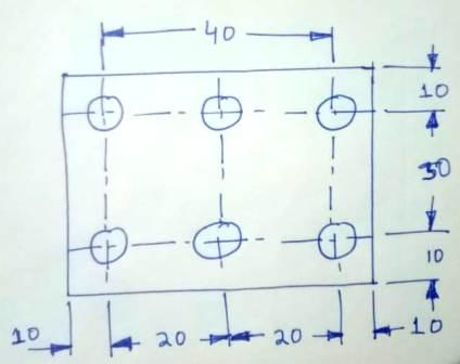
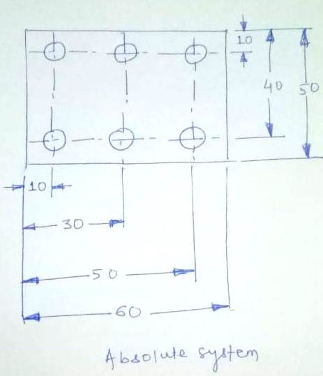
Difference between absolute and incremental programming in CNC
Incremental Dimension
Absolute dimension
CNC Positioning System
- Point To point
- Continuous path(contouring)
Point to point Positioning
Positioning(tool/spindle/Bed) from one coordinate(X,Y) to another to perform operation like drilling,Boring,reaming,taping..etc.
Continuous path(contouring)
The cutting tool travel from one point to another in Contact with work piece .Example- Turning .Milling
Zero Point Setting
Zero point can be set by any one method.
- Operator
- Manually by program
- Work coordinate
What is work offset in CNC?
This is also called work coordinate.This method is used to set zero point of the machine.Example- G54 X_ Z_.This is for master tool only.For other tool we need to set the tool geometry.
How to set work offset in CNC?
Practical of Work offset setting.-Touch the tool tip on face of raw material/workpiece and go to work offset G54 and set the Z value 0.0.Again touch the tool tip on OD of the work piece and set the X value .That is OD value.
What is Tool geometry offset in CNC?
This is the work offset for individual tool.Work offset required for other tool to perform the different operation.
What is Tool wear offset in CNC?
This offset is used to compensate tool wear.For example if there is 0.1mm of material remain after finishing cut.Then we need to input -0.1 in tool wear section and again to run the finishing cut program to remove remain material.
Interpolation
This method is the movement of Cutting tool from one point to another.
- Linear
- Circular
- Helical
- Parabolic
- Cubic
Linear Interpolation(G00/G01)
In this method the cutting tool move in a straight line.
Circular Interpolation(G02/G03)
In this method the cutting tool moves as circle or arc.This is of two types.Clockwise and counter clockwise
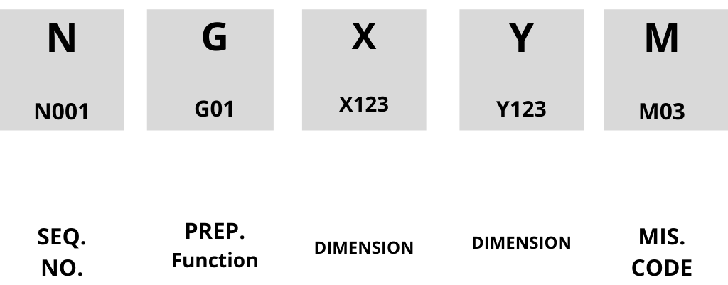
Block(CNC information)
Its consists of 5 word written in Horizontal line.This is recognized by MCU((Machine control Unit).
How to cnc programming
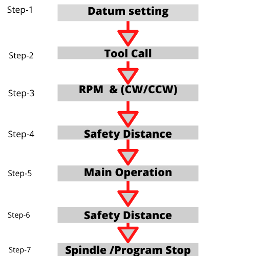
Step-1 : DATUM SETTING
Example:-
G00 G54 G90 G95 X_ Z_;
Step-2 : TOOL CALL
Example;-
T1 D1;
Step-3 : Spindle/Chuck-RPM & Direction
Example:-
M03 S90 ;
Step-4 : Safety Distance
Bring the Tool to a Safety Distance
Step-5 : Main operation
Example:-Turning/Facing/Grooving/Chamfer/Radius
G01 X_ Y_;
Step-6 : Safety Distance
Return the tool to a safety distance.
Step-7 : Spindle /Program Stop
Example:- M05 M30;
CNC programming example-fanuc(Lathe)
O0001(PLAIN TURNING)-Fanuc
N1; Sequence number
T0; Tool wear cancel
G40; Cancelling G41 & G42
G28 U0 W0; Home position
G54; Work coordinate
G92 S1000 ; Limiting speed
G95 F0.2 T0101; Feed & Tool
G96 S250 M04; Cutting speed & Spindle Rotation
G00 Z 3.0; Safety distance for Z axis.-Rapid
G00 X 56.0; Safety distance for X axis-Rapid
G1 X 50.0 M08; Turning operation & Coolant ON
G01 Z -40; Turning Operation.
G1 X 56.0; After turning operation tool will return to safety distance in feed.
G00 X 200 M09; Return to safety distance in Rapid & coolant OFF
T0;
G28 U0 W0; Return to home position
M01; Optional stop
M30; Program reset
CNC programming example-Siemens(Lathe)
G0 G54 G90 G94 X120 Z2; Datum setting & rapid movement of a tool to a safety distance X120 and Z2
T1 D1 ; Tool Selection
M03 S90 ; Speed and direction
G0 X60 Z2 ; Safety distance
G1 X50 Z0 F0.3; Starting point & feed
G1 X50 Z-220; Turning
G1 X80 Z-220; Turning
G1 X80 Z-565; Turning & end point
G1 X100 F0.4 ; Tool safety
G0 X120; safety distance
G0 Z2; Safety distance
M05 M30; Spindle stop & Program end
CNC programming lathe
Before learning about cnc programming for lathe machine we should know about the Cartesian Coordinate system.From which we can find out the coordinate point for any work piece.We should also learn about WORK CO-ORDINATE,TOOL GEOMETRY,TOOL WEAR.
CNC programming Facing
Raw material size – Diamter-20,Lenght- Any. If we want facing for 2 mm.
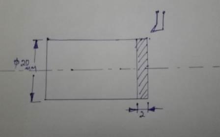
G0 X21.0 Z0.5 ; – Safety distance(Tool will move to 21.0 point in X axis and 0.5 in z axis rapidly ).20.0 is the diameter of raw material and face of work piece is the Z0.0.Tool will stop at Z 0.5 which is the distance from face.This is the suitable safety distance for raw material.After this it will start facing.
G01 Z-1.0 F0.3; – Tool will move to Z -1.0 in feed (Feed you can change)
G01 X 0.0; – Tool will move to X0.0 in feed .This is the facing operation of tool.As the tool start removing material from Z-1.0 to X0.0.That means 1.0 mm of material remove from face of the work piece.
G01 Z0.5; Now tool will move to Z 0.5 in feed.
G00 X21.0; Tool will move rapidly move to X21.0. Next to perform another facing operation.
G01 Z-2.0; Tool will move to Z-2.0 so that it can remove another 1.0 mm material
G01 X0.0; Tool will remove 1.0 mm of material from face of the work piece in this movement.
Now we can again move the tool to Z 0.5 in feed and then X21.0 in rapid.We can use the facing cycle to perform the facing operation.There we have to set the dimension to face and feed.The facing cycle will remove the material as per your requirement.
Basic of CNC programming Turning
If the Raw material having diameter 20 and lenght 30. and we want to make it of diameter 18 upto lenght 15mm.
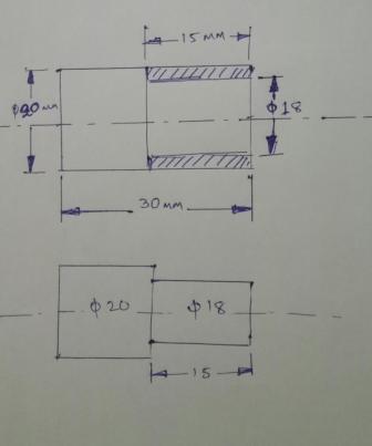
G00 Z3.0; – This is the safety distance for Z axis i.e tool will move rapidly and stop at Z3.0.Which is the distance from face.(As face of workpiece is taken Z0.0)
G00 X22.0; – This is the safety distance for X axis.
G01 X19.0; – The tool will move to 19 diameter in X axis in feed. .(This movement is for turning of 1mm i.e upto 19 diameter)
G01 Z-15; – This is the Turning operation.Tool will move from X19.0 to Z-15 with removing material.(Here you can turn ON the coolant)
G01 X22.0; – Tool will move to safety distance of x axis.
In this way you can turn another 1mm.This is the way for turning operation.
Learn Hydraulics-Click here.
Learn about Solenoid valve-Visit here.
CNC Operation & Maintenance
- Non positive displacement pump | Definition, types and examplesNon positive displacement pump is one where the fluid can be transferred by inertia of fluid,which is in motion. These pumps are make use of Newton’s first law. Advantages Initial cost is low. Maintenance cost Read more…
- Positive displacement pump type | Example,advantages and PDFPositive displacement pump type-Rotary pumps and reciprocating pumps. Example Gear pump,Vane pump and screw pump. Types of Positive displacement pump Rotary pumps Reciprocating pumps Rotary pumps Gear pump Vane pump Screw pump Gear pump External Read more…
- Positive displacement pump | Definition, Example,Types, and MeaningPressure is the primary consideration in Positive displacement pump.It can be classified as a Hydrostatic power generator. Meaning Positive displacement pump meaning it generate continuous flow of liquid to supply necessary force. Advantages of Positive Read more…
- FRL unit | Working principle & function of frl unitIn FRL UNIT “FRL” commonly stands for Filter, Regulator, and Lubricator in the context of pneumatic systems. These units are typically combined into a single assembly and serve distinct functions: Filter: Removes contaminants like dust, Read more…
- Servo motor | Working principle,function and componentA servo motor is an electro mechanical device that translates electrical signals into precise mechanical movement. It operates using a closed-loop control system(Visit here for details). It helps in maintaining accurate position, speed, and torque Read more…
- Hydraulic motor | Working principle,types,HSN codeLearn function,types,specification,hsn code,drive and piston of Hydraulic motor.Working principle and uses . A hydraulic motor is a mechanical device that converts hydraulic pressure into rotational mechanical power. It operates by using pressurized hydraulic fluid to Read more…
- Pneumatic cylinder | Parts,working principle and HSN CodeA pneumatic cylinder is a mechanical device that utilizes compressed air to generate linear motion or force.The cylinders consist of a cylindrical chamber with a piston inside.They convert compressed air energy into mechanical motion. When Read more…
- Hydraulic cylinder | Working principle,types & hsn codeA hydraulic cylinder serves as a mechanical device. It transforms hydraulic energy into linear force and motion. Operates on the principle of fluid pressure to generate force in a confined space. It comprises of components Read more…
- Control valves | Working principle,Types and characteristicsControl valves are vital components in fluid control systems. It regulates the flow rate, pressure, and direction of liquids or gases within pipelines or process systems. They manage the flow by modulating the opening or Read more…
- LVDT | Working Principle,Application & constructionLVDT – (LINEAR VARIABLE DIFFERENTIAL TRANSFORMER).An LVDT (Linear Variable Differential Transformer) is a type of electromechanical sensor used for measuring linear displacement or position. Despite its complex-sounding name, the LVDT operates on a straightforward principle Read more…
- Thermocouple | Working principle,types & applicationA thermocouple is a temperature sensor composed of two different metal wires joined together. When exposed to different temperatures at each end, it generates a voltage due to the Seebeck effect. This voltage is directly Read more…
- Thermistor | Working principle ,Application & typesA thermistor is a type of resistor that undergoes significant electrical resistance changes based on temperature. Its name is a combination of “thermal” and “resistor.” These devices are widely used in various applications. They possess Read more…
- Pressure sensors types,principle and examples.Pressure sensors are the device designed to measure and detects pressure variations in different forms. These forms include gases, liquids, or solids. It transforms these pressure changes into electrical signals or readable outputs. This capability Read more…
- Petroleum oil chemical formula | Petrol and Diesel formulaePETROLEUM OIL CHEMICAL FORMULA is is not singular due to its diverse composition. Petroleum, also known as crude oil, is a complex mixture primarily composed of hydrocarbons. Its chemical formula is not singular due to Read more…
- Strain gauge pressure sensor | Principle,use and diagramA strain gauge pressure sensor measures pressure by transforming applied mechanical force into an electrical signal. It works based on the principle that applying pressure to a material makes it to change shape. This leads Read more…
- AIR COMPRESSOR | Air compressor tank machine price,parts,typesINTRODUCTION of AIR COMPRESSOR in Pneumatic system. An air compressor is a mechanical device that transforms power into pressurized air using an electric motor, gasoline or diesel engine.It operates by drawing in air, compressing it, Read more…
- Gear motor | Gear motor types | gear motor hsn codeHydraulic and Electric Gear motor type. Hsn code and diagram.Application,advantages,disadvantages. ELECTRIC GEAR MOTOR Definition: An electric gear motor is a machine that mixes an electric motor with gears. The motor produces power, and the gears Read more…
- PASCAL LAW and its application | Pascal law derivation pdfPascal’s Law, developed by Blaise Pascal, is a crucial rule in how liquids and gases behave. SIMPLE EXPLANATION OF PASCAL’S LAW: Pascal’s Law states: Pushing or pressuring a fluid in a closed space makes that Read more…
- Bernoulli’s principle | Bernoulli principle applicationsThe Bernoulli’s theorem, named after the Swiss mathematician Daniel Bernoulli, is a fundamental principle in fluid dynamics. It describes the behaviour of an ideal fluid flowing in a streamline motion. It states that in a Read more…
- Compressed air | Compressed air system and componentsPneumatic control systems rely on a steady supply of compressed air, which must be readily available in the right quantity and pressure to match the system’s capacity. Air, the essential working medium in pneumatics, is Read more…
- Bimetallic strip works on the principle ofBimetallic strip works on the principle of co-effiecient of thermal expansion.This content describes the working principle and advantages/disadvantages of bi-metallic strips as temperature indicators. Working principles Bimetallic strip A bi-metallic strip consists of two different Read more…
- Solenoid,Valve,coil,switch,lock,formula,magnetic field and diagramLearn solenoid valve and its working principle. How its coil energized and work in lock,valve.Learn electro magnetic. What is solenoid in Physics? Introduction When we hear the word “solenoid”; our minds may conjure images of Read more…
- Power Electronics application and ScopeSome factors expand the demand of Power Electronics application are-. Energy conservation Transportation Process control and factory automation Switch mode power supply Uninterruptible power supplies Applications Aerospace Industry Resident Transport Commercial Telecommunication Utility
- Shutoff valve | Shutoff valve Symbol | Stop valveShutoff valve in pneumatic system is used to open or close the path.It has 2 ports and 2 positions.It may have a lever or handle to open and close the valve. Shutoff valve Symbol More Read more…
- Viscosity | Unit,Formula,coefficient,dimension,law and index of Viscosity
 Viscosity is the fundamental property of a fluid that describes its resistance to flow. Viscosity remains one of the most interesting and mysterious concepts in fluid dynamics. The word viscosity comes from the Latin word Read more…
 - How to calculate hydraulic cylinder force?Cylinder extension speed formula Speed(meter/Minute)=LPM X 231/Effective piston Area. Piston force formula: Force=Pressure x Effective piston area. Flow rate formula: LPM=(Effective piston area X Speed)/231 For more details-Visit here.
- FRL unit parts name | FRL unit working principleFRL unit parts name in Pneumatics system. Full form of FRL-Filter Regualtor Lubricator. Filter,regulator and lubricator are installed in a single unit call FRL unit. FRL unit parts name Air filter Pressure regulator Air lubricator Read more…
- Block diagram of a closed loop control systemBlock diagram of a closed loop control system and open loop control system shows the arrangement of interconnected control and working component.Control components are the information processors.Working components are energy converter.

- CNC LATHE MACHINES (28)
- CNC MILLING MACHINE (4)
- CNC Programming (13)
- Maintenance (45)
- Maintenance of CNC machine (73)
- Operation (17)
- Workshop Technology (22)
Automation CNC practical CNC theory Electrical Fanuc CNC Programming Hydraulic Pneumatics Siemens CNC programming
0 Comments