- Basic Hydraulic System
- Safety Procedure
- Component
- Pump & Motors
- Cylinders
- Directional Control Valves
- Relief Valves
- Check Valves
- Flow Control Valves
- Pressure Reducing Valves
- Hydraulic Circuit Symbols
- Troubleshooting
Basic Hydraulic System
The field of hydraulics has grown tremendously in the last few years. Hydraulic applications have become very diverse ranging. From a very simple lift gate on the back of a truck to a sophisticated hydraulic system.Controlling a plastic injection molding machine.
Hydraulics is actually part of a larger field called fluid power .Fluid power deals with transmission & control of energy by means of a pressurized fluid. Although it is common to think of a fluid as simply a liquid. By proper definition, a fluid is a gas or a liquid.
Hydraulics– Use oil for energy transmission.
Pneumatics– Use gas or air for energy transmission.
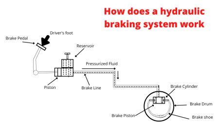
Hydraulic systems are used in a wide variety of machine application.For Example braking system in car.

The Driver apply brake through pedal.It push the piston.It pressurized the fluid .This fluid move to brake cylinder and move the brake piston.The brake piston move the brake shoe which is responsible for braking.
Safety Procedure
Some guidelines for working with hydraulic system.
| Area | Safety rules |
| Connections | Never make Hydraulic connection when its running.Check connection before starting power pack. |
| Leaks | If you found any leakage then turn off system then rectify it. |
| Moving Parts | Do not work on moving actuator,cylinder or motor.First stut off hydraulic system. |
Component of Power Pack
- Reservoir
- Electric Motor
- Pump
- Pressure Relieve valve
- Check valve
- Directional Control Valve/Proportional valve/Servo valve
- Flow Control Valve
- Actuators
- Filter
- Pressure Gauge
- Oil Indicator/Oil level sensor
- Pressure Switch
- Accumulator
- Radiator/Oil cooler
Reservoir
Hold Oil and usually act as a mounting base of components such as pump ,motor and valves.
Electric Motor
It drives Pump.It provides power to hydraulic system.
Pump
Pump creates flow of oil from reservoir to other parts of the system.It also develops oil pressure.
Pressure Relieve valve
It maintain oil pressure.It releases the excess oil to tank.
Check valve
Allow oil flow in one direction.it avoid back flow of oil when pump stop working.
Directional Control Valve
It control the movement of actuators.
Flow Control Valve
This valve control the oil flow speed.
Actuators
It convert the fluid energy to mechanical energy.Cylinders and hydro motor are the two types of actuators.
Filter
It clean the oil.It restrict the foreign particle when oil flow through it.
Accumulator
It is the back up for hydraulic system.It provide oil pressure during power failure.
Pressure Gauge
It measures oil pressure and shows.
Oil Indicator
It indicates the oil level of tank.It has two level , minimum level and maximum level.
Oil level sensor
This sensor sense the oil level and provide feed back to PLC.
Pressure Switch
It gives feed back of oil pressure.When oil pressure low, its contact changes and stop the machine.
Radiator
It is the oil cooler.It helps to reduce the oil temperature.
Chiller unit
It is used for cooling the hydraulic oil.
ELC
Electro static liquid cleaning machine.It is used to clean the oil.
LVDH
LOW vaccum dehydration machine.This machine used to separate moisture or water from oil.
Click Here for More details.
0 Comments