Schematic diagram or block diagram of hydraulic system.
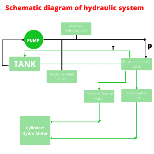
Block diagram of hydraulic system consists of
- Tank which is connected to pump set which deliver oil pressure.
- After pump pressure relieve and pressure reduce valve is connected.This valve maintain the pressure.
- Next connected to DC valve which control the direction.That is forward or reverse direction of piston or motor.
- DC valve connected to Cylinder or hydro motor through flow control valve.
- Flow control valve control the speed of piston or Hydro motor.
- Last stage is Cylinder or Hydro motor.This component execute the work.
For more information click here.
Learn CNC Programming-Visit here
- FRL unit | Working principle & function of frl unitIn FRL UNIT “FRL” commonly stands for Filter, Regulator, and Lubricator in the context of pneumatic systems. These units are typically combined into a single assembly and serve distinct functions: Filter: Removes contaminants like dust, Read more…
- Servo motor | Working principle,function and componentA servo motor is an electro mechanical device that translates electrical signals into precise mechanical movement. It operates using a closed-loop control system(Visit here for details). It helps in maintaining accurate position, speed, and torque Read more…
- Hydraulic motor | Working principle,types,HSN codeLearn function,types,specification,hsn code,drive and piston of Hydraulic motor.Working principle and uses . A hydraulic motor is a mechanical device that converts hydraulic pressure into rotational mechanical power. It operates by using pressurized hydraulic fluid to Read more…
- Pneumatic cylinder | Parts,working principle and HSN CodeA pneumatic cylinder is a mechanical device that utilizes compressed air to generate linear motion or force.The cylinders consist of a cylindrical chamber with a piston inside.They convert compressed air energy into mechanical motion. When Read more…
- Hydraulic cylinder | Working principle,types & hsn codeA hydraulic cylinder serves as a mechanical device. It transforms hydraulic energy into linear force and motion. Operates on the principle of fluid pressure to generate force in a confined space. It comprises of components Read more…
- Control valves | Working principle,Types and characteristicsControl valves are vital components in fluid control systems. It regulates the flow rate, pressure, and direction of liquids or gases within pipelines or process systems. They manage the flow by modulating the opening or Read more…
- LVDT | Working Principle,Application & constructionLVDT – (LINEAR VARIABLE DIFFERENTIAL TRANSFORMER).An LVDT (Linear Variable Differential Transformer) is a type of electromechanical sensor used for measuring linear displacement or position. Despite its complex-sounding name, the LVDT operates on a straightforward principle Read more…
- Thermocouple | Working principle,types & applicationA thermocouple is a temperature sensor composed of two different metal wires joined together. When exposed to different temperatures at each end, it generates a voltage due to the Seebeck effect. This voltage is directly Read more…
- Thermistor | Working principle ,Application & typesA thermistor is a type of resistor that undergoes significant electrical resistance changes based on temperature. Its name is a combination of “thermal” and “resistor.” These devices are widely used in various applications. They possess Read more…
- Pressure sensors types,principle and examples.Pressure sensors are the device designed to measure and detects pressure variations in different forms. These forms include gases, liquids, or solids. It transforms these pressure changes into electrical signals or readable outputs. This capability Read more…
- Petroleum oil chemical formula | Petrol and Diesel formulaePETROLEUM OIL CHEMICAL FORMULA is is not singular due to its diverse composition. Petroleum, also known as crude oil, is a complex mixture primarily composed of hydrocarbons. Its chemical formula is not singular due to Read more…
- Strain gauge pressure sensor | Principle,use and diagramA strain gauge pressure sensor measures pressure by transforming applied mechanical force into an electrical signal. It works based on the principle that applying pressure to a material makes it to change shape. This leads Read more…
- AIR COMPRESSOR | Air compressor tank machine price,parts,typesINTRODUCTION of AIR COMPRESSOR in Pneumatic system. An air compressor is a mechanical device that transforms power into pressurized air using an electric motor, gasoline or diesel engine.It operates by drawing in air, compressing it, Read more…
- Gear motor | Gear motor types | gear motor hsn codeHydraulic and Electric Gear motor type. Hsn code and diagram.Application,advantages,disadvantages. ELECTRIC GEAR MOTOR Definition: An electric gear motor is a machine that mixes an electric motor with gears. The motor produces power, and the gears Read more…
- PASCAL LAW and its application | Pascal law derivation pdfPascal’s Law, developed by Blaise Pascal, is a crucial rule in how liquids and gases behave. SIMPLE EXPLANATION OF PASCAL’S LAW: Pascal’s Law states: Pushing or pressuring a fluid in a closed space makes that Read more…
- Bernoulli’s principle | Bernoulli principle applicationsThe Bernoulli’s theorem, named after the Swiss mathematician Daniel Bernoulli, is a fundamental principle in fluid dynamics. It describes the behaviour of an ideal fluid flowing in a streamline motion. It states that in a Read more…
- Compressed air | Compressed air system and componentsPneumatic control systems rely on a steady supply of compressed air, which must be readily available in the right quantity and pressure to match the system’s capacity. Air, the essential working medium in pneumatics, is Read more…
- Bimetallic strip works on the principle ofBimetallic strip works on the principle of co-effiecient of thermal expansion.This content describes the working principle and advantages/disadvantages of bi-metallic strips as temperature indicators. Working principles Bimetallic strip A bi-metallic strip consists of two different Read more…
- Solenoid,Valve,coil,switch,lock,formula,magnetic field and diagramLearn solenoid valve and its working principle. How its coil energized and work in lock,valve.Learn electro magnetic. What is solenoid in Physics? Introduction When we hear the word “solenoid”; our minds may conjure images of Read more…
- Power Electronics application and ScopeSome factors expand the demand of Power Electronics application are-. Energy conservation Transportation Process control and factory automation Switch mode power supply Uninterruptible power supplies Applications Aerospace Industry Resident Transport Commercial Telecommunication Utility
- Shutoff valve | Shutoff valve Symbol | Stop valveShutoff valve in pneumatic system is used to open or close the path.It has 2 ports and 2 positions.It may have a lever or handle to open and close the valve. Shutoff valve Symbol More Read more…
- Viscosity | Unit,Formula,coefficient,dimension,law and index of ViscosityViscosity is the fundamental property of a fluid that describes its resistance to flow. Viscosity remains one of the most interesting and mysterious concepts in fluid dynamics. The word viscosity comes from the Latin word Read more…
- How to calculate hydraulic cylinder force?Cylinder extension speed formula Speed(meter/Minute)=LPM X 231/Effective piston Area. Piston force formula: Force=Pressure x Effective piston area. Flow rate formula: LPM=(Effective piston area X Speed)/231 For more details-Visit here.
- FRL unit parts name | FRL unit working principleFRL unit parts name in Pneumatics system. Full form of FRL-Filter Regualtor Lubricator. Filter,regulator and lubricator are installed in a single unit call FRL unit. FRL unit parts name Air filter Pressure regulator Air lubricator Read more…
- Block diagram of a closed loop control systemBlock diagram of a closed loop control system and open loop control system shows the arrangement of interconnected control and working component.Control components are the information processors.Working components are energy converter.
- Hydraulic actuators | Types of hydraulic actuatorsExample,diagram and application of hydraulic actuators.Types and principle and parts of hydraulic actuators. What is a hydraulic actuators? This is a mechanical device which transfer the force created by hydraulic fluid to some useful purpose. Read more…
- Difference between Pneumatics and HydraulicsDifference between Pneumatics and Hydraulics systems,actuators,cylinder,machines,pressure gauge and symbols. Differentiate pneumatics and hydraulics system Pneumatic system Hydraulic system 1-Pressure developed by compressor. 1-Pressure developed by pump. 2-Pressure can be stored. 2-Pressure is used immediately. 3-Pressure Read more…
- Filter in hydraulic system | Strainer and Return line filterThere are three types filter in hydraulic system.Suction filter or strainer,inline filter and return line filter. Strainer Suction filter restrict contamination of suction oil for pump. Inline filter Inline filter clean the oil after pump Read more…
- Pump cavitation | Hydraulic pump cavitation definitionWhen the inlet pressure of pump is reduced to the vapour pressure of the oil,the liquid get vaporized and cavity formed.This is called pump cavitation. Cavitation may take place when oil sucked into pump is Read more…
- Function of flow control valve | Flow control valve working principleThe function of flow control valve is to regulate the speed of actuators/piston/hydro motor. Unit of oil flow is LPM-Litre Per Minute. The volume of oil deliver per unit time is called flow.The oil flow Read more…
- Direction control valve in hydraulic systemTypes,purpose,working principle,diagram and trouble shooting of direction control valve in Hydraulic system. Purpose of Direction control valve in hydraulic system DCV are used to control the actuators.For example-Forward and reverse movement of piston can be Read more…
- Symbol of pressure gauge | Specification of pressure gaugeHydraulic Symbol of pressure gauge. For Hydraulic maintenance-Visit here. Specification of pressure gauge Type Display Working pressure range Dial size Vacuum range Operating temperature Accuracy Sensor Media Units
- Symbol of globe valve | P & ID Gate,ball,butterfly valve symbolP & ID symbol of globe valve is- For more details visit here. Learn CNC Programming and Maintenance-Click here.
- Electric symbol for motor | 3 phase motor symbolElectric symbol for motor,dc motor symbol,Induction motor Symbol. For More details-Click here. Learn CNC Programming,Maintenance of CNC Machine-Click here.
- Electrical symbol for relay | Control relay symbol | Coil symbol electricalPLC or Electrical symbol for relay or coil. It is a coil having NO and NC contact.When coil will get charged the NO will become NC.NC will become NO. For More details-Click here. CNC programming Read more…
- Pressure reduction valve symbol | Hydraulic symbol of Pressure reduction valveHydraulic pressure reduction valve symbol. In this valve Pressure line or oil flow line is block by spring pressure .When the oil pressure exceed spring pressure the oil flow line will connect. Excess oil flow Read more…
- Symbol of pressure switch | Pressure switch symbol in hydraulic systemAbove symbol is Hydraulic symbol of pressure switch.It provides feed of pressure. When the Hydraulic pressure reached to set pressure,its contact will change. For More details click here. CNC Programming and CNC maintenance-Click here.
- 4/2 directional control valve symbolHydraulic valve symbol-4/2 directional control valve symbol. In this valve there are 4 port and two positions.P is pressure port.R is return line port.A & B are application ports connected to cylinder or hydro motor. Read more…
- 4/3 directional control valve symbol and working principle3 position 4 way valve symbol or 4/3 directional control valve symbol. It has 4 ports/ways-P,T,A and B. P is pressure port.T is tank.A and B connected to cylinder. Center position is close type. During Read more…
- Symbol for pressure relief valve | Working principle of Pressure relief valveSymbol for pressure relief valve explained. Working principle of Pressure relief valve In this valve the oil will be released to tank if the pressure exceed the set pressure. Normally this valve is closed.A pilot Read more…
- Symbol of flow meter | Flow rate indicatorHydraulic/auto cad symbol of flow meter.It indicate the flow rate of fluid. For more details click here. Learn Hydraulic system. Learn CNC Programming
- Symbol of Check valve | Check valve hydraulic symbolThis is the symbol of check valve for hydraulic system.Check valve is used in hydraulic system for one direction flow. It will restrict the oil return flow. Function of check valve In this valve one Read more…
- Symbol of flow control valve,Symbol of ValvesHydraulic symbol of flow control valve.Flow control valve control the speed of piston or hydro motor. Different types of flow control valves. Check valve Shuttle valve Choke Meter in Meter Out For More details click Read more…
0 Comments